What you are looking at
One cycle of the engine is one turn of the main shaft, four turns of the crank through the 4:1 gear, and it produces one row of the table. The four turns do four different things. Press Show me and the figure poses at the middle of that turn, in whatever cycle it is in now; the readout under the card says where it is.
Turn 1 · odd into even
Δ1 → f, Δ3 → Δ2, Δ5 → Δ4, Δ7 → Δ6. Each giving column counts down to zero while the sector gears beside it turn the receiving column up by the same amount. Nothing carries yet: a wheel that passes 9 → 0 only warns the carry lever behind it.
Turn 2 · carries
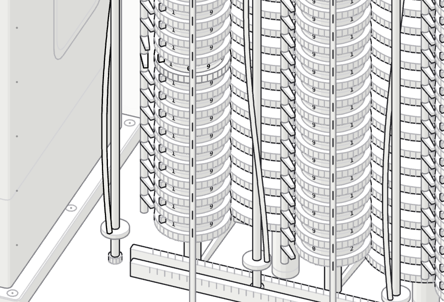
On f, Δ2, Δ4 and Δ6 a helical sweep rises from the units wheel. At every warned lever the wheel above advances one digit; if that wheel stood at 9 it warns the next, so one carry can run through a whole row of nines. The givers are restored at the same time.
Turn 3 · even into odd, f out
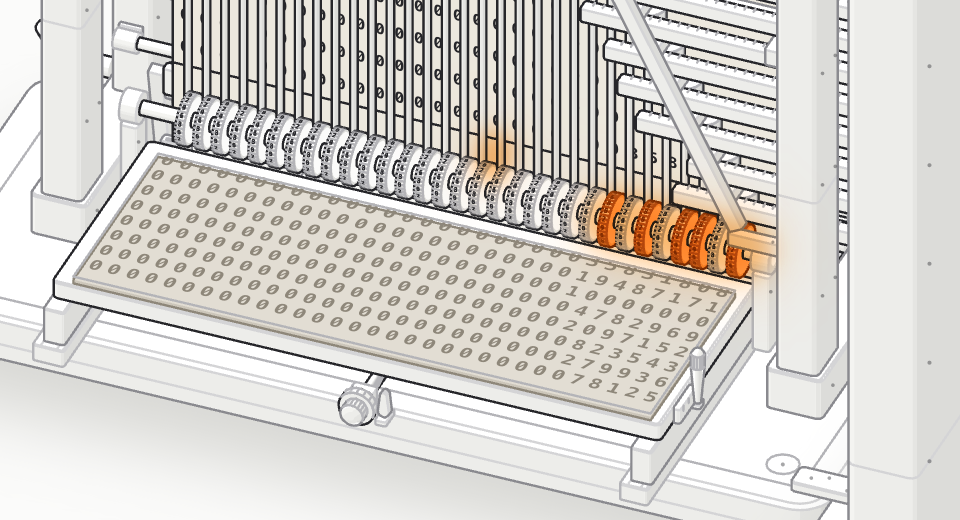
Δ2 → Δ1, Δ4 → Δ3, Δ6 → Δ5. Column f gives its value a second time, to the printer: it drops into mesh with thirty-one copy sectors and counts down, setting a row of thirty-one type wheels. At the end of the turn the platen strikes the paper onto the type and the anvil lifts the stereotype tray against it.
Turn 4 · carries
Carries on Δ1, Δ3 and Δ5. The givers are restored, f climbs back to its digits, the paper is fed one line and the tray advances one line. One cycle, one row of the table.
Why it matters
Charles Babbage designed Difference Engine No. 2 between 1846 and 1849, and it was never built in his lifetime. The drawings waited.
From 1985 to 1991 the Science Museum, London built a working calculating section to those drawings, in a project led by Doron Swade, then its Curator of Computing; the main part was finished in June 1991, for the bicentenary of Babbage's birth, and the printing and stereotyping apparatus was completed and added in 2002. The engine has about 8,000 parts, weighs about five tons and is eleven feet long. It is in the museum's collection as object 1992-556.
A second engine, completed for Nathan Myhrvold, was on display and demonstrated at the Computer History Museum in Mountain View, California from May 2008 to January 2016.
So the question Babbage could not settle, whether the design works, was settled by the people who built it. This page asks a smaller one: what does the engine look like while it is working, wheel by wheel, carry by carry? Everything you see here moves because the model says it must.
Faithful and simplified
The caption under the card is the full account. In short:
As designed
- Eight columns of thirty-one figure wheels, seven columns of sector gears between them, a carry lever for every wheel; polynomials of the seventh order in 31 digits.
- One cycle is one turn of the main shaft, four turns of the crank through 4:1 gearing. Turns 1 and 3 interleave the odd and even additions; turns 2 and 4 carry from the units wheel up, so a carry can run through a row of nines; the givers are restored.
- Column f is taken off in turn 3 by a sector gear to the printing apparatus at the left end.
- The printer makes an inked checking copy on paper and impresses the digits into a tray of soft material for a stereotype mould, with adjustable line height, columns and margins.
- Exact 31-digit registers with ten's complements for negatives; tables of functions that are not polynomials made through polynomial approximation, as Babbage's were.
This figure's own devices
- The sector lift: the real sector gears slide axially into mesh. Here the columns themselves rise or drop half a pitch into mesh with sectors set above or below the tooth line.
- The carry sweeps: real ones are helical arms on rotating shafts. Here the helices are turned by rack bars from two carry cams.
- Six cams on the main shaft: two for the carry racks, four for the printer's platen, anvil, ink roller and paper feed. The figure's arrangement, not a survey of Babbage's.
- The carry side: the levers and sweeps stand at the front-left of each column, where you can watch them work.
- The copy linkage: copy sectors, copy wheels, racks, spindles and face crowns are the figure's mechanism; the sources name a sector gear and the printer's features, not the linkage between them.
- The type wheels unwind to zero after each strike. A real printer would hold the type between strokes.
- 30 crank rpm is the figure's running speed, not a historical one.
The arithmetic is exact
The registers are eight 31-digit integers, kept as BigInts, never floats. A negative value is a ten's complement, exactly as on the wheels: a register at or above 1031 ⁄ 2 reads as itself minus 1031. Every addition is modulo 1031, so what the wheels show, what the paper prints and what the table says are one set of digits.
Setting the engine is where the trick is. The additions interleave: turn 1 adds Δ1 into f before Δ2 is added into Δ1 in turn 3, so each even difference has to run one step behind the odd one above it. The initial registers are therefore not the plain row of differences. For n3 they are f 0, Δ1 1, Δ2 0, Δ3 6, and the page derives them from the forward differences of whatever polynomial you enter.
The presets are real tables. n7 uses all eight columns, with Δ7 = 7! = 5,040; n3, n2 and x2 + x + 41 are exact polynomials, so the engine's values are exact. Logarithms, sines and compound interest are not polynomials, so they are tabulated the way Babbage's tables were, through a polynomial approximation: a degree-7 least-squares fit over the table's range, with the fit's largest error stated beside the table. For log10 x over x = 10,000 … 10,999 it is 4.45 × 10⁻⁹; for sin x° over 0 … 90 it is 4.62 × 10⁻⁸; for 1.05n over n = 0 … 50 it is 7.92 × 10⁻⁶, an exponential showing where a degree-7 fit runs out.
The logarithm table is there because Babbage published his own: Table of Logarithms of the Natural Numbers from 1 to 108,000, London, 1827, and reissued for decades. Errors in printed tables were the reason he wanted an engine at all.
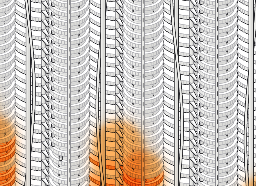
The carry demonstration above uses cycle 9 of the n7 table, where f = 4,782,969 takes Δ1 = 5,217,031: the units wheel passes 9 → 0 and a single carry runs up through 6 nines to make 10,000,000.
Check it yourself. The button below runs the model in your browser for 1,000 rows of whatever the engine is set to (or a fitted table's whole range, where that is shorter) and hands you the checking copy as a file: the engine's value, the true value and the difference, row by row. For an exact polynomial the true values are computed exactly too. Nothing leaves your browser.
How it was built
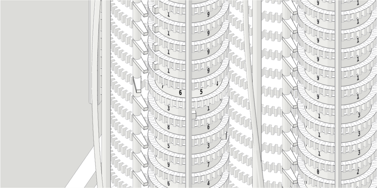
The figure is an isometric SVG written by a build script with the open-source Anatomy skill for Claude Code (MIT). Nothing is drawn by hand: a parts list comes first, every part is a small solid with four-tone shading, and the script records what it draws so the record can be audited.
- 2,221 recorded solids
- 1,375 painter's items
- 10 resting states audited
- 106,573 overlaps checked against 11,503 order rules
- 0 floating line ends
- 248 figure wheels · 248 carry levers · 31 type wheels
The audit passes when nothing passes through anything and nothing is painted out of order, and a second check walks every fine texture line and requires both its ends to land on a stroke, a dot or an outline. The model behind it all, engine.mjs, has no DOM and no geometry: registers, the cycle, the pose at any crank angle. It is unit-tested, and the page, the printer and the 3D view read from it.
The 3D view is three.js, generated from the same layout and the same part builders rather than modelled separately, and then checked against the model: 2,976 figure-wheel poses and 372 type-wheel poses compared at the end of every turn across three presets, worst error 0.000°, zero failures. It draws in 38 calls and holds 60 fps at 1440 × 900, and at 390 px wide with a 4× CPU throttle.
Glow mode, which lights whatever is working, follows April Zhu's iso-glow. With it on, the SVG spends under 7 ms of script per frame.
Sources and corrections
- Babbage's Difference Engine No 2, 2002, Science Museum Group Collection, object 1992-556: the engine itself, its dates and its dimensions.
- Difference engine, Wikipedia: the method of differences, the four-step cycle and the sector gear to the printer, the Science Museum build of 1985–1991 and the printer of 2002, the Myhrvold engine, parts and weight.
- The Babbage Engine, Computer History Museum, in particular The Engines and A Modern Sequel: the printer's stereotyping and formatting, the modern build, and the exhibition of May 2008 to January 2016.
- Charles Babbage, Table of Logarithms of the Natural Numbers from 1 to 108000 (London, 1827), scanned at the Internet Archive, with the 1831 and 1841 editions.
- Doron Swade, The Cogwheel Brain (Abacus, 2001), published in the United States as The Difference Engine: Charles Babbage and the Quest to Build the First Computer (Viking, 2001; Penguin paperback 2002, ISBN 978-0-14-200144-8): the story of the build by the curator who led it. See Doron Swade on Wikipedia.
Where the figure departs from the design, the caption under the card says so and the list above says what is the figure's own. If you work with the real engine, at the Science Museum or anywhere else, and you see something wrong here, tell me. Corrections are credited.
Credits
Built by Kevin Owens with Claude Code. Figure built with Anatomy by wheresryan22 (MIT). Glow mode after iso-glow by April Zhu (MIT). 3D view with three.js (MIT), vendored at 0.160.0 so the page loads nothing off-site.
Licences: Anatomy · three.js · dark figure · 3D view